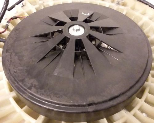
| Motor |
 |
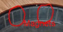
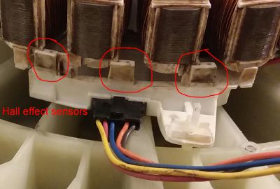
The permanent magnets in addition to powering the motor also turn the Hall effect sensors on and off.
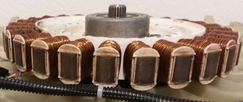
Under the rotor are the coils.
There are 9 coils for each phase.
There are 3 phases for a total of 27 coils.
| Inside of motor drum |
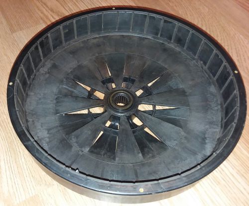 |
| Magnets inside motor drug |
 |
| 27 coils or electromagnets - 9 for each of the 3 phases |
 |
The 9 coils for each phase are wired in series.
| 27 coils or electromagnets - 9 for each of the 3 phases |
 |
| Hall effect sensors - one sensor for each of the 3 phases |
 |
| Bread board to test Hall effect sensort |
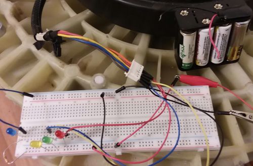 |
Each phase, A, B, C or 1, 2, 3 has a Hall effect sensor to tell when the phase should receive electricity.
These LEDs just light up when the appropriate Hall effect sensor turns on or off.
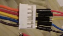
| Connector to Hall effect sensors |
 |
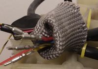
| Connector to the coils or electromagnets |
 |